Medusa rev. B vs rev. A changes:
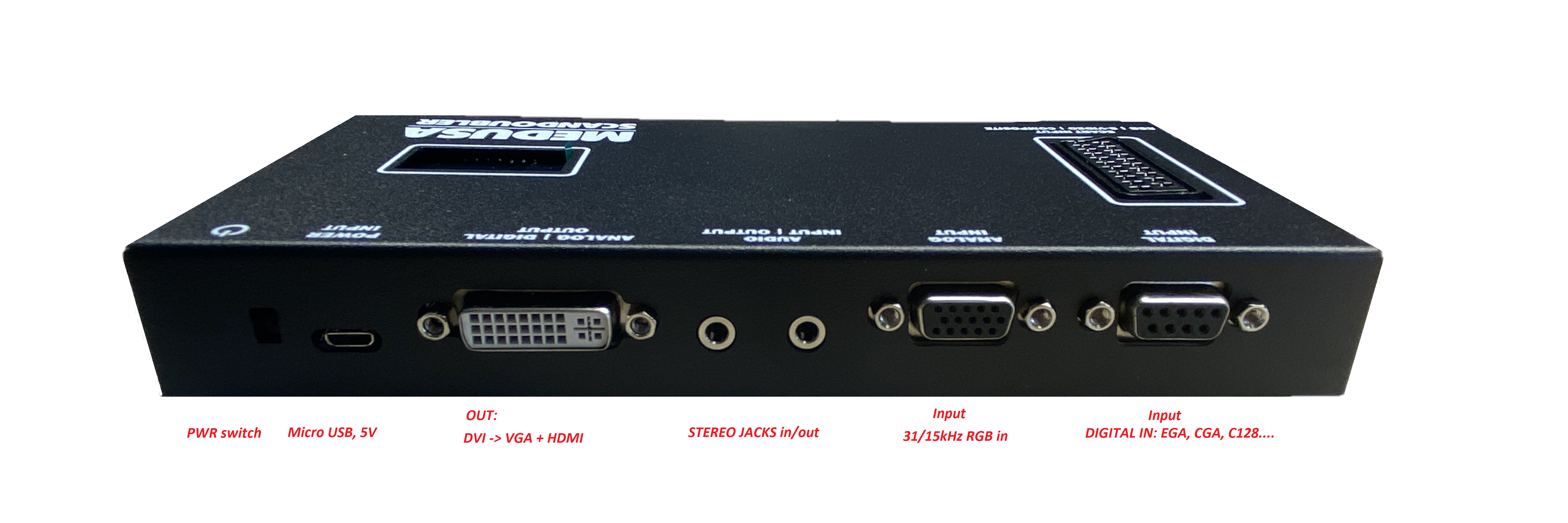
- new db9 socket - 8bit digital input. Ready for supporting C128, CGA, EGA, Apple IIc and others
- moved audio source switching from CPU to FPGA - gives ability to mix both channels using PWM
- added new PLL to generate audio sample frequency (switching between 32k, 44.1k, 48k, 96k, 192k etc.)
- better op-amp that drives audio output jack socket (32ohm headphones can be connected directly, also better audio quality)
- lowered digital audio amplitude (cleaner, not overdriven audio over DVI)
- 5V voltage on DVI passed through Schottky diode (prevents powering Medusa from DVI)
- better input protection on SCART socket (better protection of fragile NCS2564)

Medusa is here; after many experiments with framemeister, OSSC and others, we decided to make quantum leap ahead all competition and make sth MUCH BETTER :-).. and to be honest - WE DID IT !
Medusa project was started 6-7 years ago, when 2 people - old retro stuff geeks have met - Acidmaker (creator of Sio2sd and proffesional file system used at Harvard, Columbia university and many others) and me. Since very beginning Acidmaker was into gettting perfect picture from ATARI ST / ATARI 8bit / Amiga. Meanwhile, me (lotharek), as opposite side, was into simple usage, ergonomy and user friendly interface. After 5 long years of develomennt, many protototypes, hours of discussions/testing, thousands of euros spent (obviously...) we are very happy to announce, that final project is coming and it is about to be released in preorder for retro community soon.
What we are about to offer:
- device, that converts picture from retro systems to modern displays, that utilise dvi output (with small/cheap adatper also HDMI with sound)
- device, made at my automatic lines, that represents highest standarts of smd/THT assembly
- device in metal case with nice oled lcd
- OSD !!! both on small lcd and displayed picture
- addidtional completly NEW approach to picture settings (usb connection PC-MEDUSA) via terminal banging.
- easiest worlwide firmware flashing (just connect medusa to PC/MAC via usb)
- Medusa accepts almost all SIGNALS that retro computers can produce:
- composite ( yellow chinch, via scart)
- Svideo (via scart)
- RGB ( via scart)
- RGBHS ( via vga connector, separat syncs)
- 2 functional jack 3.5 mm stereo - working as insput and output
- DVI-I output (DVI / DVI with audio modes) port working in many modes: along with adapters: DVI_I it supplies vga and digital picture, thus old crt monitors as well as modern TVs may be used ( THE SAME TIME - DUAL DISPLAY MODE wth proper splitter)
- hundreds of slots for customers display sets
- at the momnet of relase, MEDUSA will detect and properly will display following systems in all available formats:
- Spectrum familly
- Spectrum 128k
- Spectrum 48k
- Pentagon
- Amstrad
- Commodore 64
- Atari XL/XE
- Atari VBXE PAL
- Atari VBXE DP
- Atari VBXE NTSC
- Atari VBXE DN
- Atari ST
- Atari ST PAL
- Atari ST NTSC
- Atari ST HI
- Atari Falcon
- Atari FALCON VGA (this is standard VGA 640x480 - maybe will be changed in the future)
- Atari FALCON N40
- Atari FALCON N80
- Atari FALCON PAL
- Atari on MIST
- Amiga OCS
- Amiga ECS/AGA (without VGAonly)
- Amiga EURO36
- Amiga EURO72
- Amiga SUPER72
- Amiga DblNTSC
- Amiga DblPAL
- Amiga Multiscan
- Amiga SUPERPLUS
- Amiga HIGHGFX
- Amiga HD720
- Amiga ECS/AGA (with VGAonly)
- Amiga DblPAL*
- Amiga DblNTSC*
- Amiga EURO72*
- Amiga Multiscan*
- Amiga SUPER72*
- MIST
- MIST MENU
- MIST QL
- MIST C64 PAL
- MIST C64 NTSC
- MIST C16
- MIST VIC20
- MIST ACORN
- MIST MAC PLUS
- Macintosh (tested on LC475)
- Mac 512x384
- Mac 640x480
- Mac 832x624
- Mac 1024x768
- Mac 1152x870
- Standard VGA
- Special modes (unrecognised PAL-like and NTSC-like)
FUTURE PLANS:
- we are counting on You! please support us - we want You to test all devices /consoles You have. Let us now what video modes shall be added to firmware. We are sorry, we cannot add all available systems to device at the moemnt of sale as we do not have all retro systems
Power supply:
- micro usb mobile phone charger (5V, 500 mA minimum)
Inputs:
- compoiste video ( via scart)
- S-VIDEO (via scart)
- RGB (via scart)
- RGB via VGA input ( separate syncs)
- component ( via scart and vga)
Otput:
- DVI-I (digital and analog output via adapters )
- Audio out (jack stereo)
- AUDIO IN (jack stereo)
- DUAL VIDEO OUTPUT with DVI split cable /not offered/ - VGA and DVI the same time
Buttons
There are three buttons "left", "middle" and "right".
- Standard functions
- "left" - "up"
- "middle" - "down"
- "right" - "enter"
- Special functions (when both RGB and SDTV signals are detected - LED is yellow)
- "middle" - switch between RGB and SDTV input.
- Special functions (after power on)
- "right" alone - enter "firmware updater" - usually you do not need to do that manually - firmware updating application does this automatically for you
- "left" and "middle" together - factory reset (blue LED should be on for a couple of seconds)
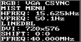
Info on OLED
- used A/D chip (RGB or SDTV) and input (SCART/VGA for RGB and S-VIDEO/CVBS for SDTV) or firmware version when there is no input signal
- detected mode, for RGB name of the system ("Atari ST PAL", "Amiga PAL" itp.), for SDTV detected signal standard (PAL, NTSC, SECAM with type) or "NO INPUT SIGNAL"
- Horizontal frequency of input signal
- Vertival frequency of input (and output) signal
- Flags (such as LINEDBL - line doubling)
- Current DVI window (you may think of it as a "resolution")
- Screen shift horizontal:vertical
- Working Pixel Frequency
|
|
 |
Front LED color
- Red - RGB signal detected
- Green - SDTV signal detected
- Yellow - both signals detected (RGB on VGA and SDTV on SCART) - in this mode you may switch input using "middle" button
- Blue - firmware flash / clearing settings
- Nothing - no input signal detected
- DVI to HDMI cable is sold separately - please, check RELATED ITEMS TAB
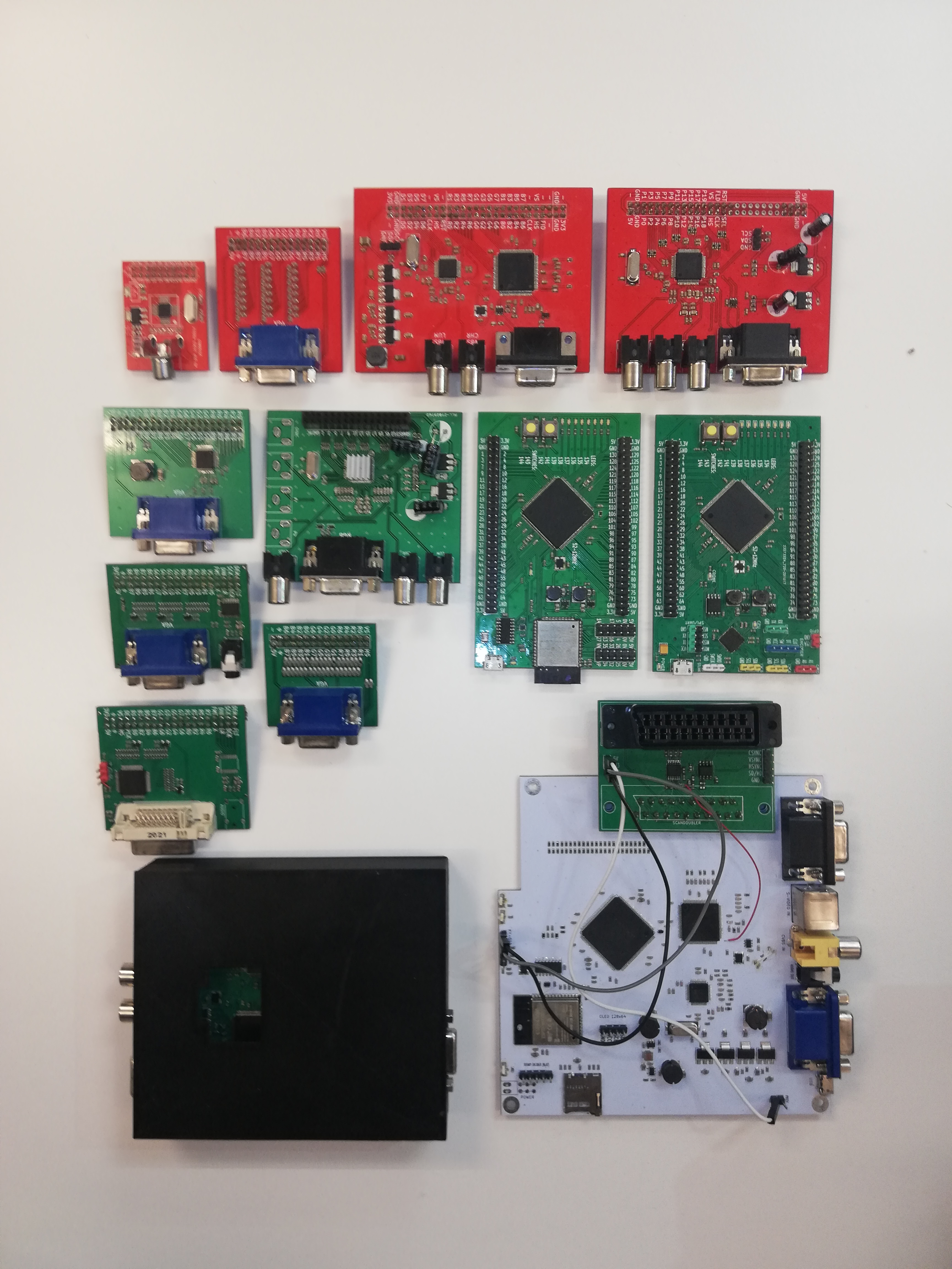
Some history - 5 years at one picture :-))

Product gallery
First, please refer to offcial WIKI PAGE: http://medusa-sc.org/index.php?title=Main_Page
Q. Do you possibly have a manual or pin assignment for the SCART connection? Unfortunately, no information can be found on the website (Medusa).
A. MEDUSA`s SCART pinout is ...SCART STANDART and is widely described around the web. it can be found in many places; example: https://en.wikipedia.org/wiki/SCART
Most important informations below:
 |
| |
| Pin 1 |
NOT USED AT MEDUSA |
Audio output (right) |
| Pin 2 |
|
Audio input (right) |
| Pin 3 |
NOT USED AT MEDUSA |
Audio output (left/mono) |
| Pin 4 |
|
Audio ground (pins 1, 2, 3 & 6 ground) |
| Pin 5 |
|
RGB Blue ground (pin 7 ground) |
| Pin 6 |
|
Audio input (left/mono) |
| Pin 7 |
|
RGB Blue up
S-Video C down[a]
Component PB up[b] |
| Pin 8 |
NOT USED AT MEDUSA |
Status & Aspect Ratio up[c]
- 0–2 V → off
- +5–8 V → on/16:9
- +9.5–12 V → on/4:3
|
| Pin 9 |
|
RGB Green ground (pin 11 ground) |
| Pin 10 |
NOT USED AT MEDUSA |
Clock / Data 2[d]
Control bus (AV.link) |
| Pin 11 |
|
RGB Green up
Component Y up[b] |
| Pin 12 |
NOT USED AT MEDUSA |
Reserved / Data 1[d] |
| Pin 13 |
|
RGB Red ground (pin 15 ground) |
| Pin 14 |
NOT USED AT MEDUSA |
Usually Data signal ground (pins 8, 10 & 12 ground) |
| Pin 15 |
|
RGB Red up
S-Video C up
Component PR up[b] |
| Pin 16 |
|
Blanking signal up
RGB-selection voltage up
- 0–0.4 V → composite
- 1–3 V → RGB
|
| Pin 17 |
|
Composite video ground (pin 19 & 20 ground) |
| Pin 18 |
|
Blanking signal ground (pin 16 ground) |
| Pin 19 |
NOT USED AT MEDUSA |
Composite video output
S-Video Y output |
| Pin 20 |
|
Composite video input
S-Video Y input |
| Pin 21 |
|
Shell/Chassis[e] |
Q. Hi, i’ve recently recieved my medusa and i was wondering if there is a discord or forum (I’ve seen the wiki) to join to help in testing and reporting with various computers and consoles as i have a few. From X68000 to CDi .
A: we think about this to develp further firmware revisions. Meanhwile help us sending fingerprints to Jakub Kruszona-Zawadzki <acid.maker@gmail.com>
http://medusa-sc.org/index.php?title=Menu#rgb_only
fingerprint - Medusa recognises input devices using "fingerprint" mechanism. For each device there is a predefined fingerprint in the firmware. But sometimes it may happen that your device is not recognised correctly, or it is not in Medusa's database at all. This option displays fingerprint parameters for currently connected device. These values may be used by Medusa developers to improve devices detection and adding new ones.
Q. Just tried my CPC6128 using the retrocomputershack scart cable. Medusa recognises the source as S-VIDEO which is incorrect, should be RGB and the image is very very dark.There doesn’t appear to be an option to change the source input from Component/Video/RGB ect.
A: Medusa will recognize rgb, when at 16 of scart is proper voltage. that is how scart standarts works. If You see svideo as detected signal , it means clerarly you do not switch Medusa`s scart to rgb mode. Only green and red signals are passed to Medusa... but inside not proper chip works with signal ( composite/svideo instead of vga/rgb). Your medusa led is GREEN. it shall be red when RGB is detected (WIKI). Modify cable to follow scart standart (amstrad cables need extra power to supply proper voltage) as CPC6128 doesnt supply voltage at video out connector. More at wiki:
https://www.cpcwiki.eu/index.php/File:CPC2SCART_-_RGB.jpg

.png)

