Please, check our SMD/THT services - smd.lotharek.pl; from idea to ready devices
One 24 × 52 mm board replaces the ULA, all the RAM, the sound chips and the RF modulator.
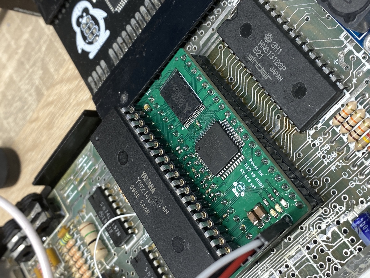
SuperULA drops straight into the ULA socket of any Issue 2–6 ZX Spectrum 48K. It does not emulate the Z80 — it drives the real CPU already on your board, generating its clock, interrupts, reset and memory timing exactly as the Ferranti chip did. Everything around that CPU is rebuilt in an FPGA: memory, video, paging, sound and storage.
No cut traces. Four wires. And the machine that boots is whichever machine you tell it to be.
Replaces
Adds
#FFFD / #BFFD portsFour personalities, each with correct video timing, memory map, contention behaviour and I/O decoding — not approximated, regenerated from first principles.
| Mode | Video timing | RAM |
|---|---|---|
| ZX Spectrum 48K | 312 lines, 224 T/line, 69888 T/frame | 48 KB |
| ZX Spectrum 128K | 311 lines, 228 T/line, 70908 T/frame | 128 KB |
| Pentagon 128 | 320 lines, 224 T/line, 71680 T/frame | up to 4 MB |
| Timex TC2048 | 312 lines, 224 T/line | 48 KB + SCLD modes |
48K, 128K and Timex keep their original memory sizes. Extended memory is available exclusively in Pentagon mode, across three paging schemes.
Mode 00 — Profi (1 MB) Ports #7FFD + #DFFD. Page = {DFFD[2:0], 7FFD[2:0]} → 64 × 16 KB. DFFD D3 enables all-RAM mode; D4 unlocks the 7FFD paging lock.
Mode 01 — Pentagon 1024 (1 MB) Ports #7FFD + #EFF7. Page = {7FFD[5], 7FFD[7:6], 7FFD[2:0]} → 64 × 16 KB. EFF7 D2 switches 7FFD D5 between bank-select bit (1 MB) and paging lock (128K). D3 enables all-RAM. Verified against AUMT memory tester, option 1.
Mode 10 — Pentagon + Scorpion (4 MB) Ports #7FFD + #1FFD. Page = {1FFD[7:6], 1FFD[4], 7FFD[7:6], 7FFD[2:0]} → 256 × 16 KB. Full 4 MB addressing with Pentagon-compatible base paging. Verified against AUMT memory tester, option 6.
Standard ULA rendering includes cycle-accurate memory contention, the snow artefact on 48K/128K, and the FLASH attribute — the timing quirks that games actually depend on.
Timex SCLD is implemented in full:
#F4 paging registerULAplus provides a 64-colour palette via ports $BF3B / $FF3B, held in on-chip block RAM and read back correctly by software that queries it.
Output is 9-bit RGB (3-3-3) with composite sync, digital, straight to the adapter board.
Behind the ULA sits a PSRAM controller running at 56 MHz across a 23-bit address space, fronted by an intelligent arbiter.
The arbiter juggles three masters — CPU reads, CPU writes and video fetches — and adds a prefetch engine that speculatively pulls the next likely byte while the bus is idle. Write buffering, request ageing and prefetch invalidation are all handled in hardware, so the Z80 stalls as rarely as physically possible.
Shadow ROM. All ROM images live in PSRAM, not in an EPROM. At power-on SuperULA copies 32 × 16 KB ROM slots (512 KB) from SPI flash into PSRAM. The physical ROM socket is still used when external device pages it`s rom - below
External ROM auto-detection. SuperULA probes N_ROM_CS at boot. If a DivMMC-style interface is present, it steps back and lets that board own the ROM space. If not, it serves ROM itself. No jumpers, no settings — it works out what it's plugged into.
This is the part worth understanding, because it explains the whole board.
SuperULA streams RGB, composite sync, the entire Z80 bus and every audio enable flag off-board over a custom 8-bit synchronous link running at 56 MHz — a framed, self-synchronising protocol. At the far end sits the second FPGA, on the supplied RGB adapter board.
That adapter turns the stream into the picture and the sound. The AY chips, SAA1099, Covox and SounDrive all live there, watching the Z80 bus in real time, and their output leaves on the same Mini-DIN9 connector as the video.
One cable out of the Spectrum. Video and stereo audio, both digital-clean, both from the same link.
Every audio device is individually switchable per profile — you decide which machine gets which chips.
You store four independent profiles in flash. Each carries its own machine type, ROM set, memory configuration, ULAplus enable and full audio device selection.
Press the button and the screen goes black: SuperULA takes over the video and the CPU, and shows you a menu.
//ONLY WHEN NO EXTERNAL ROM DETECTED; if detected - config.tap must be loaded/
There is no keyboard controller involved. While the CPU is held in reset, SuperULA drives the highest address lines itself and reads the keyboard matrix directly — the same trick the ULA has always used, turned inward.
Two seconds after every reset a discreet Profile: banner appears in the lower border, so you always know which machine you booted.
Pick a profile and the machine reboots as a different computer. Instantly.
You never need an external programmer. SuperULA exposes the SPI flash to the Z80 through ports $00F3 and $01F3 — ROM images and configuration can be rewritten from a program running on the Spectrum.
Configuration is stored with a magic header, version field and XOR checksum. If the block fails validation, SuperULA falls back to safe defaults rather than booting into a corrupted state.
The FPGA bitstream itself updates over USB-C.
| FPGA (main) | Gowin GW1N-2 |
| FPGA (RGB adapter) | Gowin GW1N, QFN48 — video + sound |
| Link between them | Custom 8-bit synchronous, 56 MHz |
| RAM | 64 Mbit (8 MB) PSRAM, BGA, bottom-mounted |
| ROM | 32 Mbit SPI flash |
| Bitstream update | USB-C |
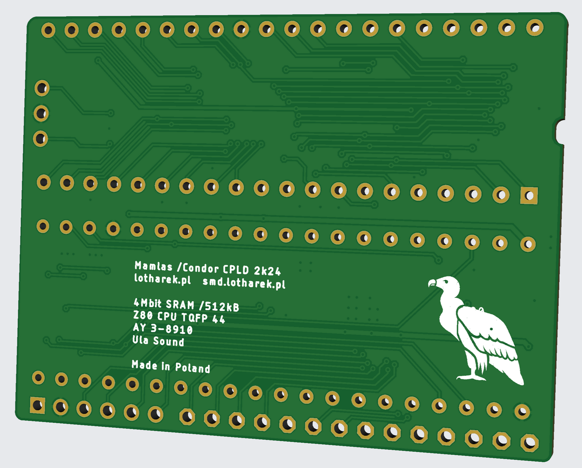
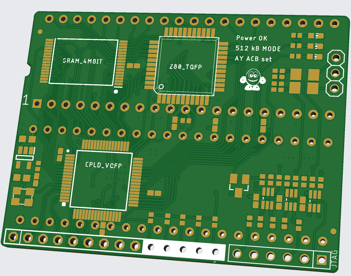
| PCB | 4-layer, 24 × 52 mm, double-sided |
| Video out | 9-bit RGB (3-3-3) + CSYNC, via Sega Mini-DIN9 adapter |
| Wires to Z80 | 4 — M1, RESET, IORQ, RFSH (all active low) |
You will need: soldering iron, desoldering pump, steady hands.
Works with external DivMMC, DivIDE, Kempston joystick interfaces and other edge-connector peripherals. Directly compatible with ESXDOS for SD card mass storage.
SuperULA does not produce composite or YUV video. RGB only.
Direct connections only. No electronics between the SCART and Mini-DIN pins.
| Signal | Mini-DIN | SCART |
|---|---|---|
| RED | 7 | 15 |
| GREEN | 3 | 11 |
| BLUE | 1 | 7 |
| CSYNC | 4, 5 | 20 |
| AUDIO LEFT | 8 | 2 |
| AUDIO RIGHT | 9 | 6 |
| BLANK | 2 | 16 |
| GND | 0 / shield | 4, 18, … |
In the reference photo, the pin shown as +5 V is in fact the blanking signal — ignore the label.
Every clock-domain crossing is explicitly constrained. The bus snapshot, memory arbiter and CPU clock generator are timed against real, verified multicycle relationships rather than blanket exceptions. The design closes because it is correct — not because the analyser was told to look away.
ONLY DIRECT CONNETIONS ! no electronics between pins of scart and mini din.
| SIGNAL NAME | MINI DIN | SCART | REMARKS |
| RED | 7 | 15 | direct connection |
| GREEN | 3 | 11 | direct connection |
| BLUE | 1 | 7 | direct connection |
| CSYNC | 4, 5 | 20 | direct connection |
| AUDIO LEFT | 8 | 2 | direct connection |
| AUDIO RIGHT | 9 | 6 | direct connection |
| GND | 0 / SHIELD | 4,18, ...... | direct connection |
| BLANK | 2 | 16 | direct connection |
ps. below picture shows +5v - ignore value, it is blanking signal.
Real hardware video: Sr_ULA + MEDUSA + Bizon
Inside BOX: